Hey there, sorry for the delayed response. I appreciate your reply.
After some digging it seems my issue was with the PATH, easily resolved with a reinstall of Python and a quick tutorial on Environmental Settings and Windows Command Prompt.
I’ve been working on the Tape screen lately and encountered some interesting animations - line weights changing when switching screens during recording, colors not changing as expected, and some other randomness.
Do you have any insights as to where the animations are coded?
I didn’t find anything in the code of the display SVG files that would indicate they’re animated, so I assume it’s coming from an external file. Some of the animations, like on the neck part of the CWO screen (bode.svg) appear to be simply alternating layer visibility, while other parts respond to signal flow to move points of a path (the circular top left portion of the guts).
Any helpful information is appreciated.
Thanks in advance.
lol. Those are pretty nice. Totally breaking the design philosophy that TE had for the display, but fun.
Do you have any insights as to where the animations are coded?
yes. This is all coded in C++ files which are compiled into the final firmware. So basically in the blackbox that is the firmware and we can’t do much about it.
I guess if you’re lucky, most of the vector manipulation in code is done relative to the current position of the vector being changed. If it is absolute positioning, you will have no luck changing the SVG around because they will jump where the code tells them to be.
==> you will have to experiment to find that out (and the community would appreciate documenting that as well )
Thanks for the reply!
Yeah, I strayed from the TE aesthetic a bit, mainly to see what was possible. All my files are within 3kb of the original file sizes, sometimes smaller but usually larger. However, saving with 2 decimal places rather than 3 will reduce file size and still function.
I have noticed that complex Bézier curves tend to cause odd visual glitches, but not consistently from screen to screen. That may have something to do with how the animation is dictated.
So far all of the animations seem to be based relative to paths rather than absolute to screen coordinates. I won’t be attempting to dive into C++ anytime soon.
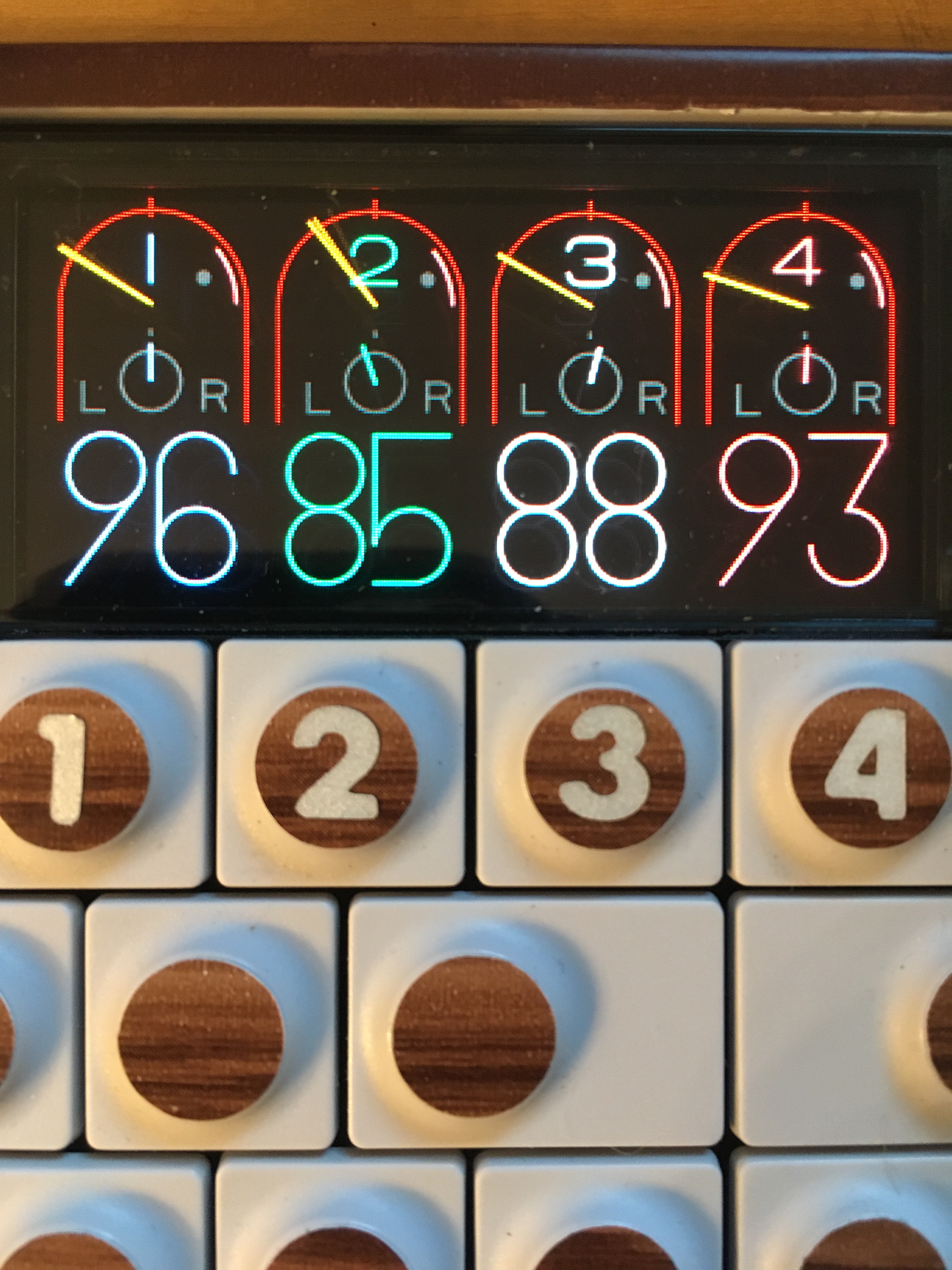
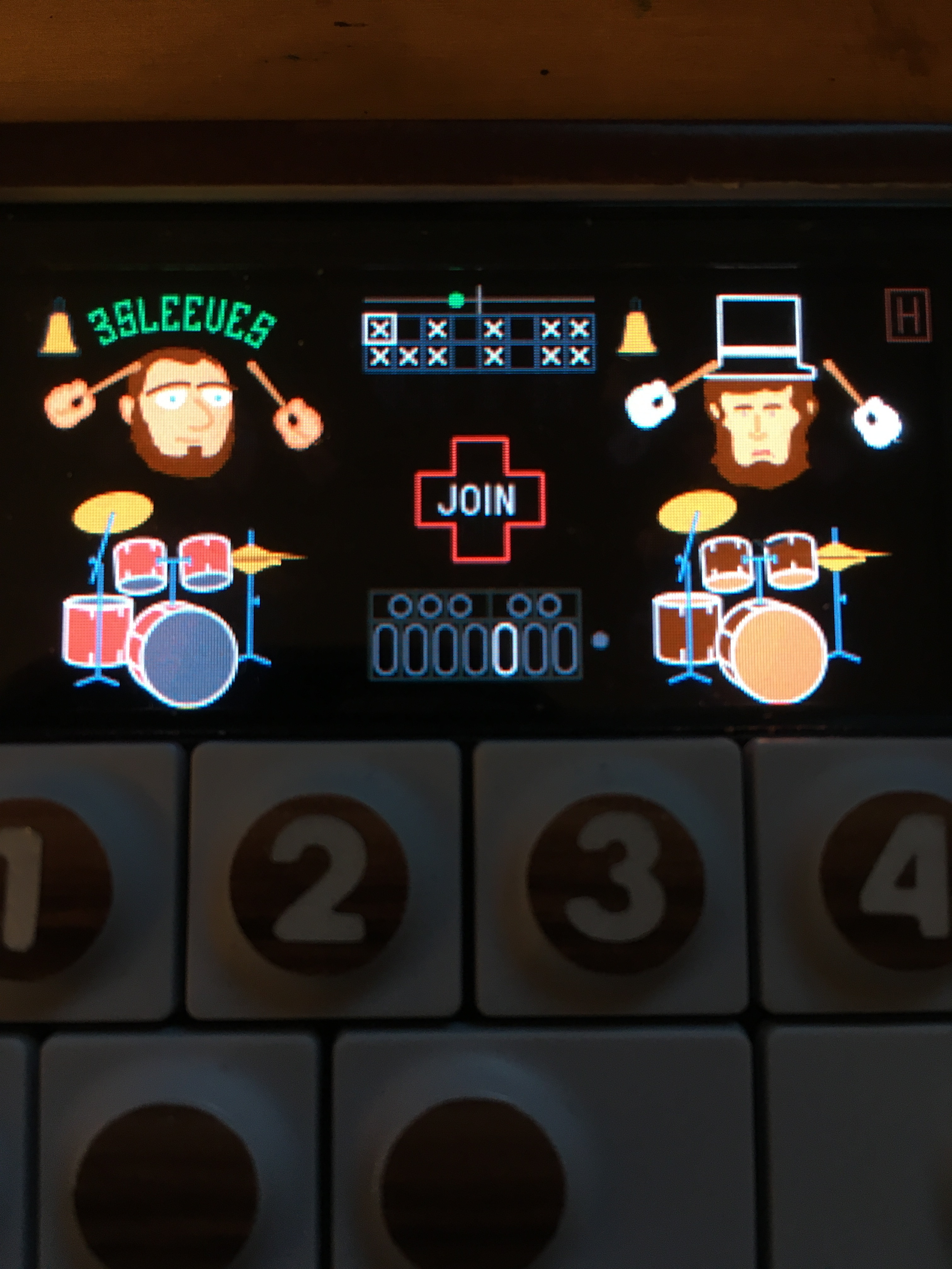
Also I’m finding that web safe RGB colors render inconsistently, especially darker colors. I haven’t messed with the SVG that is essentially a swatch palette yet, but from what I can tell that is what dictates the colors of active animations on various screens, such as the outline around the cowbell on the drummers or the L and R by the pan pots of the mixer screen.
Soon I’ll try manipulating the SVG that dictates the fonts for the GUI, but my plan is to keep the characters within the same dimensions as the current ones to avoid overlapping text and numbers.
It’s been a wild ride so far!
I’ve realized just how much screen burn comes with 4 years of use as shadows of the standard tape graphics are visible on every screen now. It’s most prominent on screens with solid color fills.
If anyone is interested in these edited SVG files let me know, I can try to make them available on GitHub later…of course I assume no liability for whatever happens if you use them in your own custom firmware😉
Just wanted to share my awe and gratitude for the knowledge and skill in this thread. Seriously impressive, and evidence of one of the reasons the OP-1 has been so long-lasting IMO - the community.
I just got one the other day and was having trouble seeing the tape at the bottom. Being able to flip it to the top is a god-send. The installation was easy af. Plus, the Moose is cool too.
Hey just been thinking about trying to get some movement in the iter engine.
has anyone tried to see what happens if we copy for example the cluster engine svg file. Then rename the copied file to iter.svg? would we then have the iter synth running with the cluster skin?? or would this just not work at all?
trying to workout if the svg files are tied to the encoder knobs or the engine itself
if they are tied to the encoders we could just edit another engines svg to look abit more unique and use it for iter
let me know what you guys think
also has someone made a easy way to swap out default presets with custom ones or are we all just editing them in manually
All possible “states” of the animation are in the SVG file, the firmware code just switches them “on” and “off” (which is an attribute in the SVG paths)
example that comes to mind: Finger sequencer Dudes/Apes
The animation is more complex and the firmware fully modifies/recreates the actual path info inside the SVG file
example that comes to mind: strings synth
In my very first posts way back when I showed modified animations in the finger sequencer. Those were done by leaving the “id” of all paths/layers intact, only changing shapes and colors and position.
This is fairly easy.
So if you want Iter to do anything you are depedend on the IDs of SVG pathes which the firmware manipulates. In case of Iter probably almost none if I remember correctly. Thats why there is only the mod by Wavi which has very little animation going.
Rearranging is totally possible (see Tape screen mod) but in the end, you will always be stuck with only being able to change the “canvas” while the “paintbrush” is wielded by the firmware.
I think with Iter the size and color of the 4 dials could be changed, but almost anything else would need to be static. The shape of the needle in the dials could maybe be altered, sort of like a novelty watch with funny hands…if that makes sense. As the legendary @TabascoEye has said, the layer/path IDs in the SVG would need to stay in tact regardless.
Hey there. Trying to do some edits. It has not worked. Are there any rules for the SVG art layers apart from name? That’s what you mean by the ID, right? Does it need a certain number? Does it load each one individually ?
Thanks in advance.
Well in the end, only TE knows those rules.
In my case, we used the same software (Adobe illustrator) so the “layout” of the SVG file did not significantly change (as it does when using e.g. “Inkscape”).
Just be super careful about removing shapes and instead try to modify them only.
Check the content of the SVG (the textual content) against the original for any major discrepancies.
(use some diffing tool for that, Meld, Winmerge, diff,…)
Note what the error message says, sometimes it indicates a particular layer or stroke/object parameter that can give you a hint as to where the issue lies within the SVG. It can take some trial and error. From looking at your screenshot it kind of looks like you used a brushstroke on the heads, that may be part of the issue since the stock SVG always has a uniform stroke width (only the volume slider on the tape screen seems to allow for varied stroke weights in my experience).