there is a strange micro switch that has no purpose. its right next to the big switch but its just not far enough not to be triggered. it makes no sense.
as an experiment: i have jamed peace of paper to trigger that micro switch and put it back together and put back into op-z. how ever after debugging the connections with micro atwitch activated inside op-z, i have found no change.
maybe its still left over from an old revision on this PCB board.
neat, some interesting design in there. I wouldn’t have expected the flex PCBs on the I/O jacks, but that makes sense given the thin form factor (would take up more height to mount them on the green PCB)
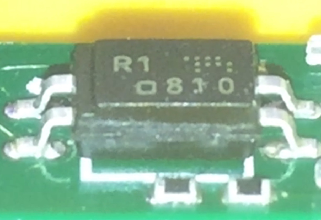
Optocouplers aren’t surprising—it’s part of the MIDI spec, and it would be irresponsible not to include them. They’re primarily to avoid grounding noise issues, not for electrical protection.
Are you sure that switch isn’t triggered? Maybe it just has a lot of overtravel (triggers way before the lever is fully actuated)
Could be something for debug use, e.g. for the module to know when it’s not actually mounted in the housing. Or it could just be for a feature they planned for but threw out in the end.
i love discovering easter eggs inside teenage engineering stuff. i learn something new every time.
Method of a connector not being physically attached to main board is very smart. people used to build electronics that way long time ago, but there days connectors are usually attached directly to the pcp, making them a weak point due to connector being moved all around while in use.
inside op-z there is even more impressive way of use of flex-pcb. the headphone connector is made out of op-z mine enclosure, so its all in one peace of the frame mold, while only connecting pins are on flex-pcb.
im still not sure about the redundant micro switch inside op-lab. it does go in, but only very slightly, ±10% , i have assumed it not enough to trigger it. but you probably right. … maybe it acts like an optocoupler, but with out the LED, to insulate the circuit better. its only for clock connector, hope there is some cool function behind.