The arrow does not make sense to me either!
I wished I had time and motivation to finish my custom firmware… 
The arrow does not make sense to me either!
I wished I had time and motivation to finish my custom firmware…
Does anybody have a non-functional PO-33 or PO-35 collecting dust? I would like to update the info at http://hackingthepo.weebly.com with the HW differences for the metal series but never found a picture of the components under the display for those models. If you have one and is willing to help here, it should be fairly easy to remove the display by cutting the pins with a nail trimmer or small plier. Just make sure to take a hi-res picture so I can read the components markings.
Btw, I put this same plea over reddit but got no answers.
@punji
I have a PO-35 that doesn’t turn on…
I was somehow hoping at some point it’ll come back to life. I’ll look for it and get back to you!
@RisingSon That would be awesome! I feel bad for you, I love my PO-35… I have a PO-28 that also refused to power-up. I even tried to reflash it, but it simply did not work at all. I suspect some component gave up, or a solder joint got cold. Well, at least I can use it for parts in case some other PO get a fault button or pot.
@punji
Thanks for the condolences. But luckily I found a second hand one quickly after in a pack with a KO which wasn’t too bad… With 2 KOs I’m ready for any disaster.
Curious what has been uncovered about the PO-32 microtonic encoding system. For example, could you configure a non-whole number BPM in Microtonic and transfer this setting to the PO-32?
Hello! I just removed the screen from my ko-33, the problem now is it won’t start… nothing happens, batteries is new. Any chance to using it without the screen? How to diagnose?
Thanks on advance!
How did you remove the LCD? Did you desolder it or just cut the pins?
Anyway, it should have worked unless:
For the first too you may try inspecting the board visually and using a multimeter to check it. The last one is hard to confirm, you would need an oscilloscope to check the initialization of the codec.
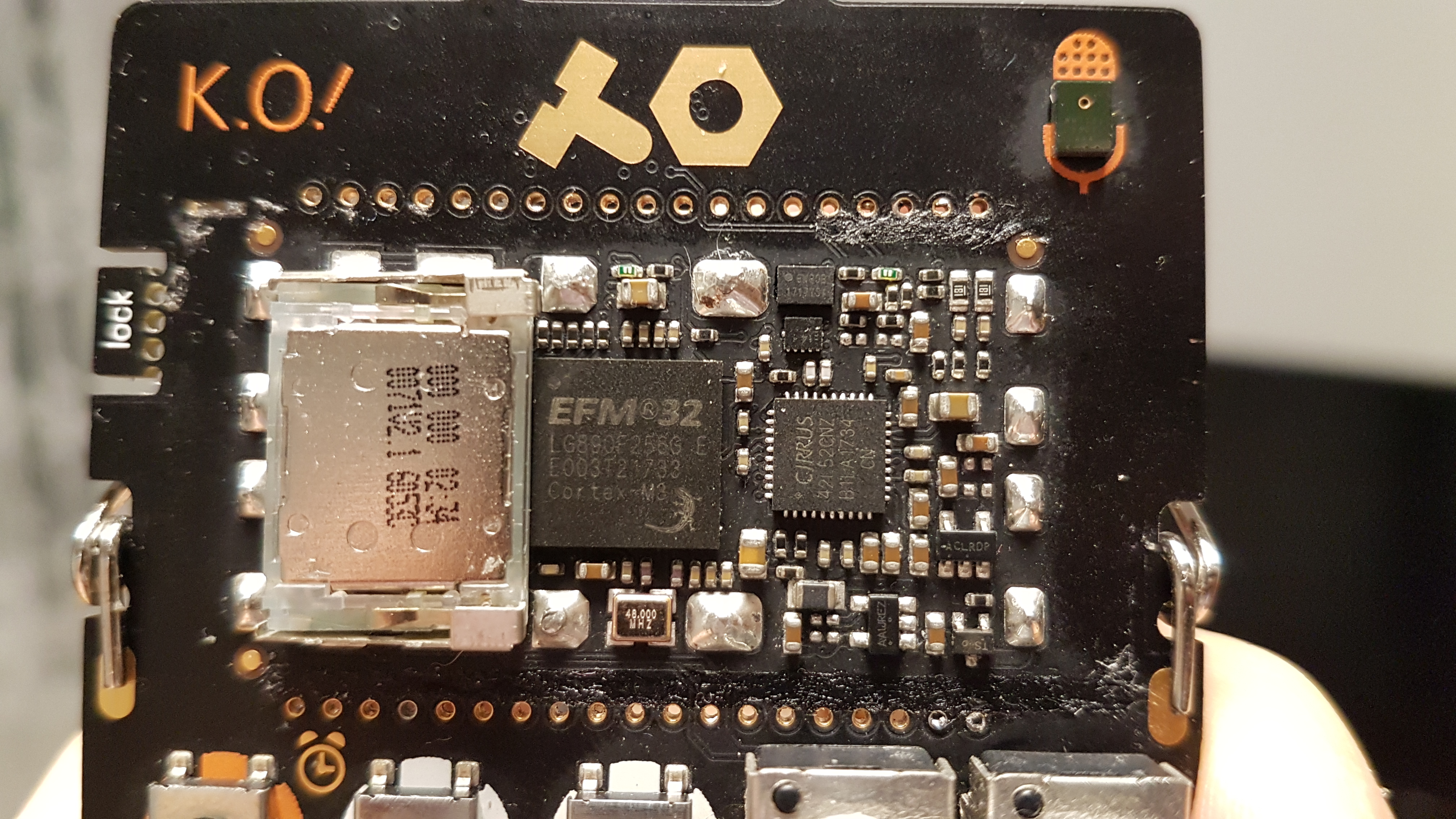
By the way, could you please share a picture, if possible a close-up of the circuit?
I desolder the screen (as careful as i can).
About loseness… the components are so tiny, i dont know how to diagnose, probably need a lens or microscope.
Short circuit - perharps, but how to probe (i have a multimeter).
If static, it must be baddest case for me. Im not specialist and take it to service would cost same as good ko-33 from second hand
I have a PO-35 with a broken screen.
I’m planning to buy a working second-hand unit and try to reverse-engineer the pin-segment mapping and design a minimalistic LED-based replacement screen. I have a microscope so I can share pictures of ICs with you if you still need them.
It would be great if you could share any tips that could help me with segment mapping. Do you think it’s possible to do it without desoldering the working screen? AFAIK these LCDs should be driven with AC, but I don’t have a source, can I use DC temporary? Any insights in addition to what you have on hackingthepo will be much appreciated…
It has been quite a while since I did that but, yes, it is possible to do the mapping without desoldering the display. You definitely need an AC source, I used a PIC or similar board running a very simple program to just toggle two GPIO pins at the proper frequency. This is from my page at hackingthepo.weebly.com:
“The display is multiplexed. Common pins are 1-4, segment pins are 5-38. The LCD driver is configured to 32Hz refresh rate, 1/3 bias quadruplex multiplexing (8x 4ms), low power waveform, 3.28Vpp.”
I don’t quite recall the procedure, but I had a conductive rubber pad that I used to touch the common pins with one phase and a probe for exploring with the other phase. Reading the EFM32 datasheet about LCD multiplexing helps.
Thanks for advice! I ended up using my phone with a function generator app to generate a 50 Hz square wave with 180 degree phase shift on L and R channels, and used this signal to drive LCD, worked like charm.
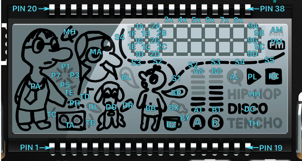
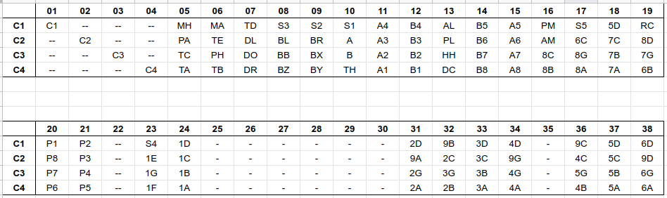
Here I mapped the segments of PO-35. If you want, feel free to add this to hackingthepo.weebly.com, I’d be happy if this info will help somebody. Here is the table as a spreadsheet.
Awesome!
Check this document for the LCD waveforms:
https://www.silabs.com/documents/public/application-notes/an0057.1-efm32-segment-lcd.pdf
Not sure this is of imediate help to anyone, but I thought it belonged in this thread: https://teenage.engineering/pop-report
Accidentally found out TE had some competition with quite a few mods. None as intense as what punji is after, but might appeal to circuitbenders.
Hey @punji, great work with the documentation.
I would be interested if you need any help with the custom firmware.
I mostly do iOS and cpp stuff, recently reverse engineered the SP-12 MIDI communication and the Antelope Orion Studio control software. This sounds like a great challenge.
You can find me on Instagram @rmri.beats . Let me know!
Wow, it’s been 5 years since I worked on that last! I actually never released any code because it was still in early stages, but I should have a backup of that somewhere. I guess it would required some migration work just to get started again, since I was using Keil RTOS and I’m not sure if that was a wise choice.
Anyway, the two major reasons I stopped working on that project were:
1- You need a flashing tool to Install the custom firmware. I think it would be necessary to create a small board with pogo pins that plugs into the PO pads area and does that, instead of requiring people to buy an EFM32 starter kit that costs $100 and install the SiliconLabs IDE. That board would need its own micro-controller and firmware, complicating things further. The good thing about that board is that it could be used as a co-processor/memory extension to augment the PO hardware. Fir example, it could have RAM for implementing a delay, or ROM for implementing a wave table, or even a USB interface and work as a pen drive to add sample audio files or patches.
2- I was not sure what that custom firmware would do. Implementing all the basic PO functionality is a lot of work (engines, sequencer, sync modes, pattern backup, automation, etc). What could it do that would be not so complicated and still interesting enough? At one point I started exploring creating a sampler, but then the PO-33 was released. Other options I considered at the time were: MIDI controller PO (not sure if that makes sense), DX7 compatible PO (cool but there are so many devices like that already), effects processor PO (probably the easiest to implement since a sequencer may not be required), looper PO (in case the flash board provides extended RAM).
Does that make sense? Do you (or anyone) have any ideas?
@punji thanks for the reply.
I’m personally looking for a hardware platform with audio IO and hardware buttons/controllers where I can focus on the code without worrying about the hardware.
The PO seems optimal in that it is widely available, portable and not too complex.
Other candidates are the LXR drum machine and Mutable Instruments modules.
These cost more and are non portable so it’s less rewarding.
I have many ideas I want to try, especially around sequencing that I didn’t see in any of the POs. I’m happy to buy the dev kit to conduct my experiments.
I was also always disappointed that none of the POs had any actual games.
It might be a memory limitation, but still.
I agree with you, I just wish TE would provide an SDK with a stripped down PO firmware for those like you that wish to explore new ideas for the sequencer, effects or sound engines, but I guess they don’t see any reason to spend their time on that because there is not a lot of people into it. Again, it will take a big effort just to get a custom firmware to that bare minimum (including performance and stability) necessary to do something useful. It may be more realistic to look elsewhere, unfortunately.
I actually found an alternative:
Never heard about it before but it’s a DIY open source shield for the Teensy.
More ram, faster CPU, USB, perfect for prototyping. I will look into that now.
I remember looking into that project a long time ago, it definitely sounds a good option.