Hello! I am currently moving to a different country and have been unable to continue on the file but I can upload my current kicad file to GitHub in two to three days and will share it here for collaboration. I also have detailed pictures of the whole pcb unfolded now and will share those two for easier layout and measurement. I’m glad with any help because the layout until now has been really slow. The pcb is very difficult to recreate since it has lots of cutouts that are difficult to measure and get right but with combined effort it should be easy.
1 Like
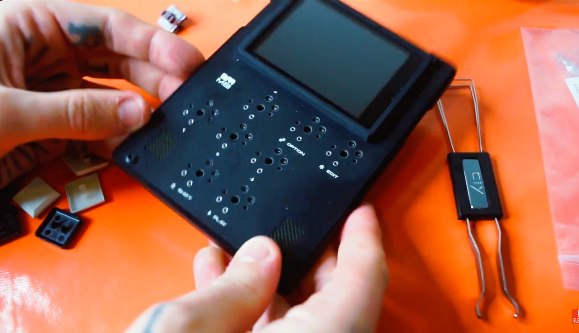
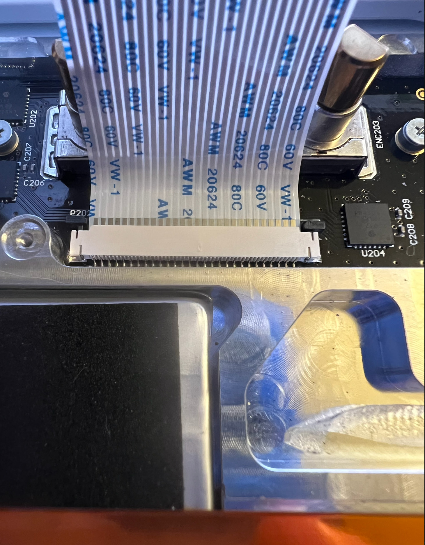
The ribbon cable is attached to a whole pcb that is folded and needs to be recreated. The failure point are the traces on the pcb. The traces are between the two folds. I think the rubber domes could be reused from the old pcbs or sourced.
1 Like
My pc is still in shipment but should be here tomorrow or the day after. I will share the kicad files on GitHub so we can collaborate on it. I think I have the basic measurements of the pcb down now and am currently working on the cutouts of the individual rows/buttons and would love some help since I’m a little slow with the move and everything.
1 Like
Awesome! Thank you for the response.
I’m putting together my own go at it in KiCad now, just to learn the software. Had a thought: What if, while we’re redesigning it, we make a couple improvements?
- proper bonded two layer flex pcb, to avoid delamination like in the original
- some other more durable trace material like copper
- switch from crappy rubber domes to something more robust and serviceable like the tactile SMD switches used below. They might fit, and if they do they’re going to feel SO much better than squishy domes.
2 Likes
One thing I’m still wondering about is if the new op-1 field keyboard is compatible with the old one. I would still much prefer to recreate it since the design of these traces is flawed and will need replacement in a few years again, but, since the button layout looks to be the same and the tear downs look similar I’m just wondering if the field keyboard has just optical changes but same functionality and hardware design.
1 Like
Yes that sounds great. I’m also trying to get more familiar with kicad since I’ve never used it before. I can send you my files and we can consolidate them on your GitHub.
I don’t use Discord that much but here is a server:
1 Like
The iFixIt site specifically calls out that the OP1 keyboard is incompatible with the Field. So I assume the opposite is also true.
1 Like
Switched over to EasyEDA, as it has easier support for flex pcbs through JLCPCB.
Ribbon cable spec is 28 pin, and 1mm pitch.
Got the switch locations completely locked down:
- Default keyspacing is 15.5mm for 1U keys
- Longer white keys are halfway between rows 5 and 6. So just add/subtract 7.75mm on y axis.
- Black keys are either on 1.5U (23.25mm) OR 1.25U (19.375mm) spacing on x axis from its neighbor. If it’s a long distance, it’s 1.5, and if it’s the shorter spacing it’s 1.25.
Next up is defining the cutouts, and pathing.
2 Likes
Some key options:
-
Top left is the Kalih choc v1 keycap. It does fit, but the keycaps will sit above the stock locations. Could be solved with an additonal trim perhaps. Big advantage here is they’ll feel amazing, and they’ll also be very servicable and customizable. Want linear? clicky? Go for it. If i did this approach, would just do a standard PCB and ditch the stock backplate and switches.
-
Second option are the small switches listed above.Will keep stock height. Unsure if there’s clearance issues with the existing scissor switches. Still, way better reliablity and feel vs the stock domes. Decently serviceable as they’re smd.
-
Third option is to remake the stock domes/membranes. I’m concerned here that there will be wear and service issues down the line, and that sourcing and applying the domes by hand will be tricky.
My gut says option B, but want to hear other opinions too.
2 Likes
That looks great. I’m At 33% with the cutouts I would say.
I think option 2 sounds great but I’m willing to invest a little into a switch version!
1 Like
Ok, wild idea here, but what if instead of trying to cram something into the original space that the scissor switch is, we do what dirtywave did here and make a clean panel with hotswap plugs?
Would be waaaaayyy simpler to design and manufacture, bulletproof reliable, and user customizable. Wouldn’t look flush like the original op1, but honestly the m8 looks sick, and feels amazing compared to the op1’s keys.
Then we can just skip all the bs around fiddly cutouts, scissor switches, sourcing domes (which seems to be impossible). And anyone with broken scissor switches or dome mechanisms is covered too by this with one easy swap.
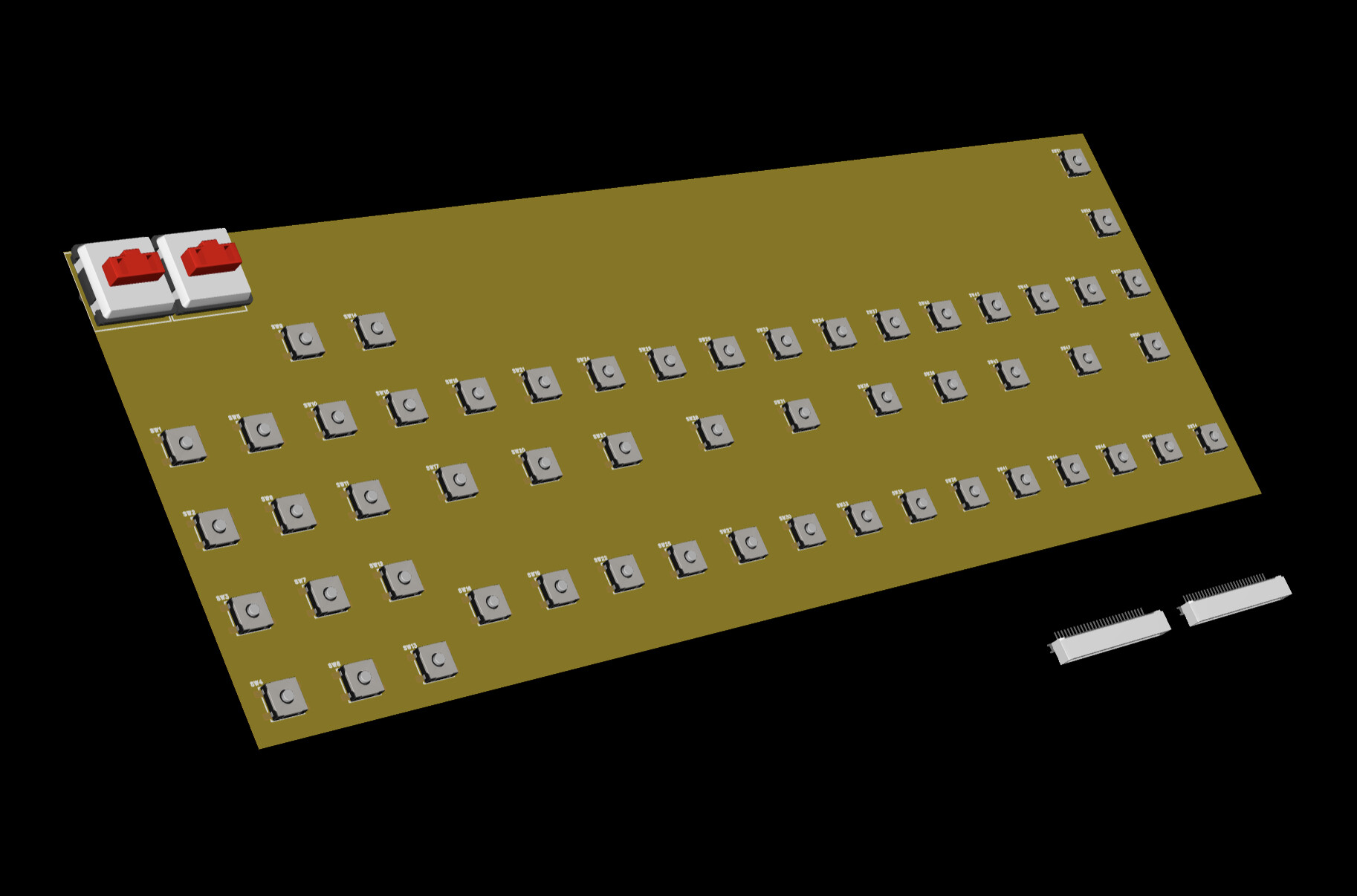
Here’s a mockup of what a slot-in hotswap board might look like. Just like the M8, the idea is the main unit is flush, and then Kalih PG 1350 “choc” switches plug right in and stand proud of it. Will be a different look from the original, but will look pretty sick imo if we do it right. And super bonus, will be easily reversible.
2 Likes
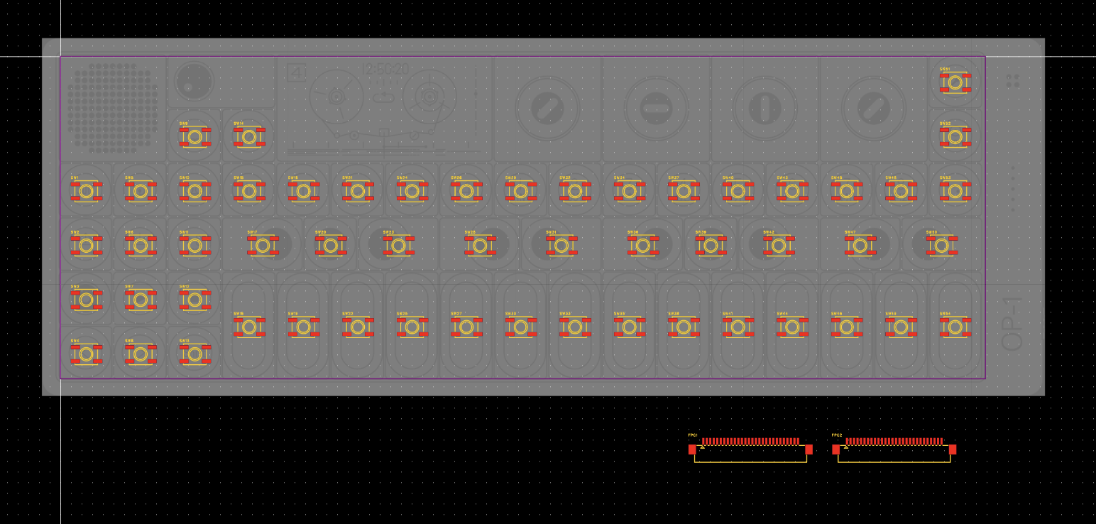
More Updates:
-
the connectors are compatible with standard 28 pin, 1mm pitch ribbons. See image A. Here is one example on Amazon Amazon.com: MECCANIXITY Flexible Flat Cable Extension Ribbon Cables 28 Pins 1.0mm Pitch 150mm for 3D Printer, Laptop, Camera, Screen and DVD Player Connector A Type Pack of 4 : Tools & Home Improvement
-
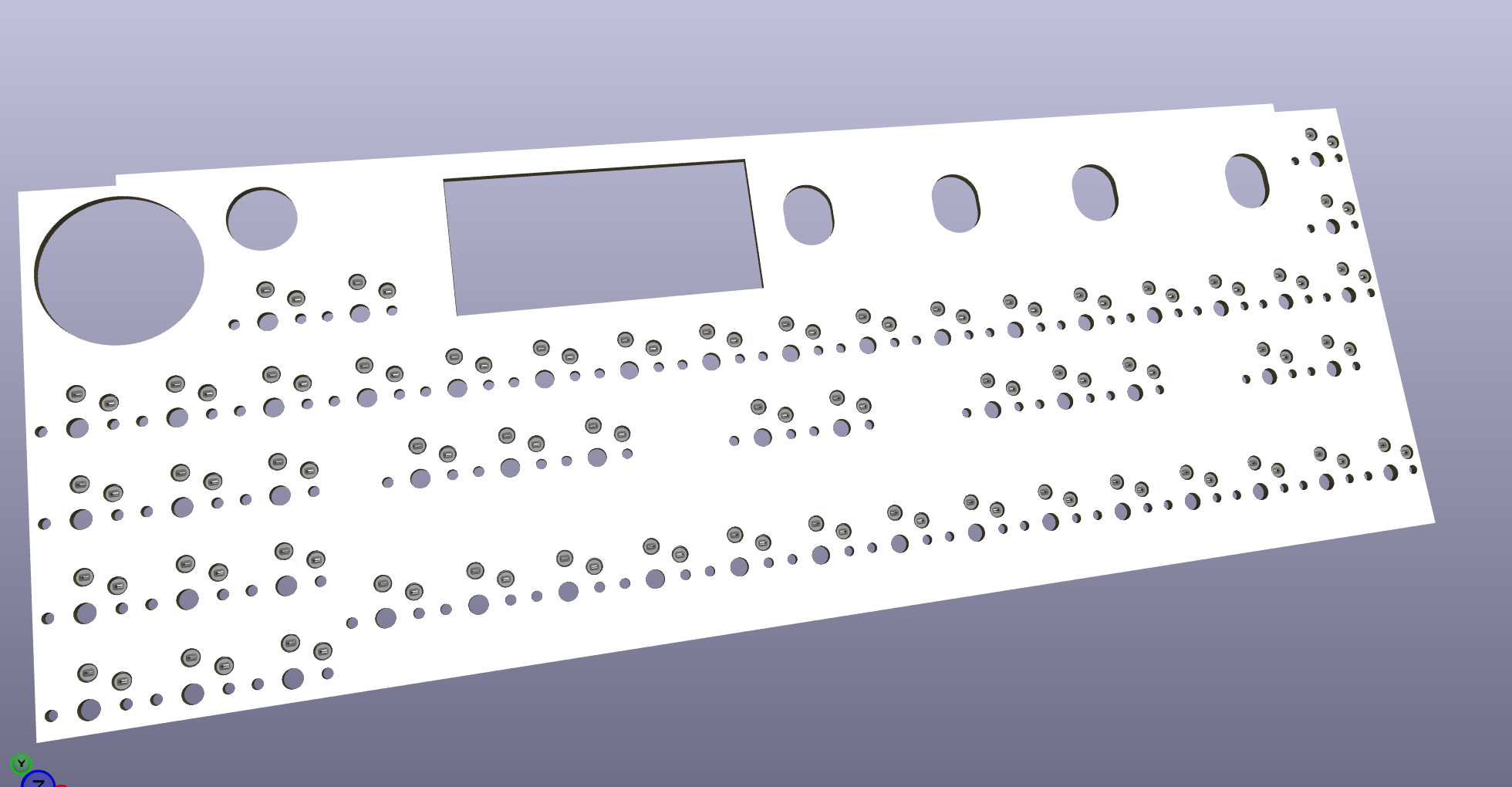
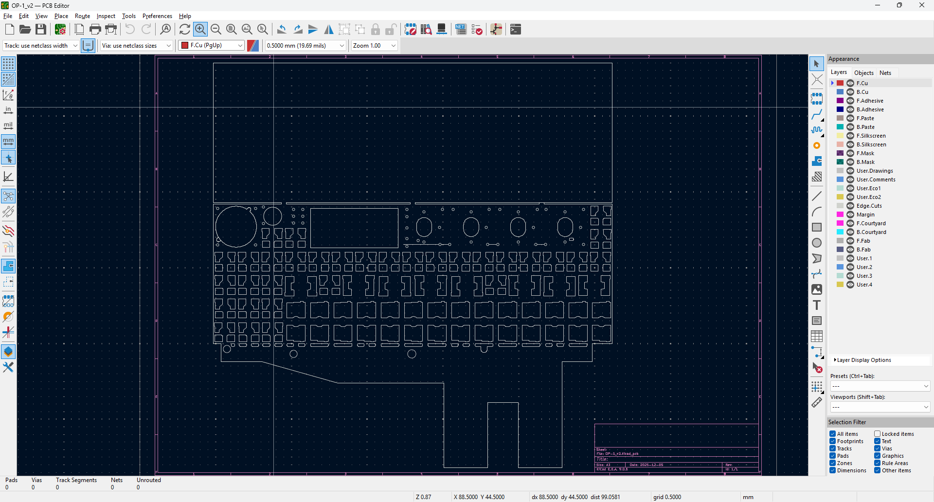
Major cutouts are done. See image B. The big challenge for the mechanical kb design is that we’d need to source 15mm keys (a very small nonstandard design), or we’d need to make an adapter for the original ones to fit the PG1350 sockets. I think the latter is the best option.
-
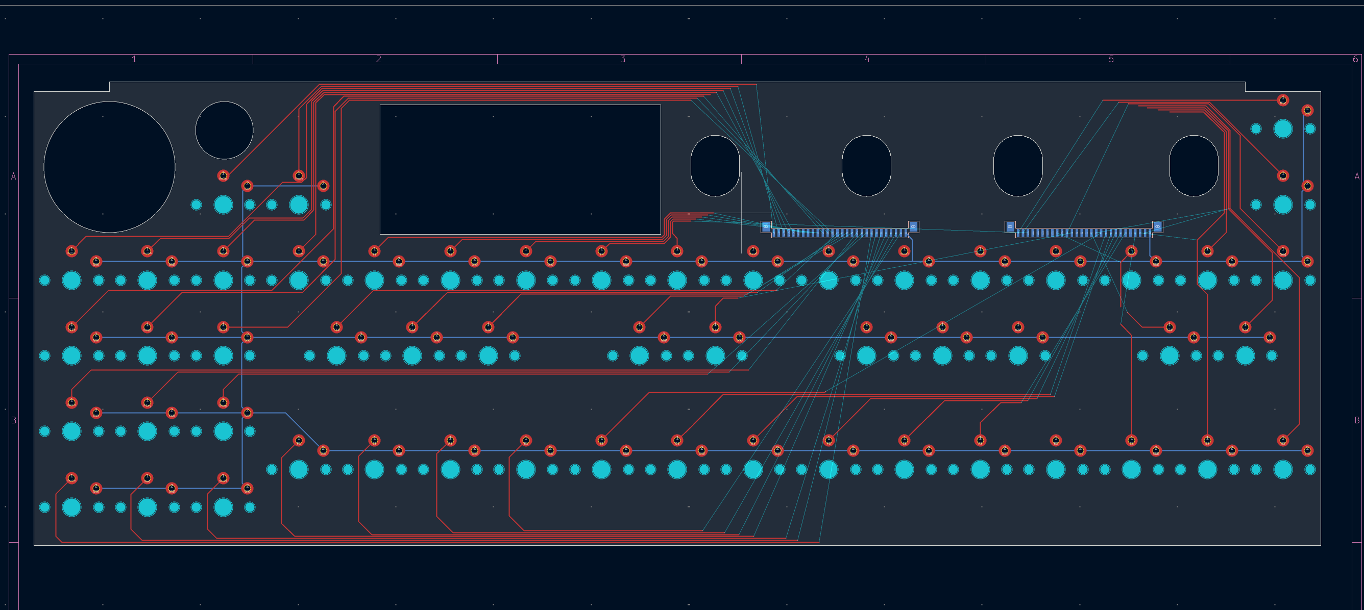
Traces are going to be really crammed. It’s clearly going to have to be a 4 layer. Just not enough room with how dense the layout is. The original design fits 4 traces max between the keys fwiw.
1 Like
That’s amazing work! I uploaded my kicad project to github but I think its not the latest file, im still unpacking and need to find the backup drive. I’m looking into that. Here is the github link: GitHub - akod1ng/OP1KBD: Teenage Engineering OP-1 Keyboard Replacement · GitHub
@surfacenormal : How would you like to proceed? Would you even need the recreated original design if we go for a 4 layer pcb? Or does it make sense to try to recreate the existing design and then go from there (mechanical etc.)?
Imho, a drop in replacement with as much original parts as possible would make sense for most people having that issue.
I also tried to recreate the traces as mod file for kicad but im unsure on how to apply that.
Here is a very helpful online trace map I used for that (credit goes to user whatnot https://op-forums.com/u/whatnot):
2 Likes
Heck yeah! Thank you for sharing. Will check out tomorrow.
I agree that a flexible pcb, but done with proper metallic traces, would be ideal. The issue there is sourcing and adhering the domes. Three problems:
- They’re unobtanium
- idk if you’ve tried removing the original ones, but you are definitely going to damage them.
- They need to adhere around the circular base, without adhering at the center. It’s super fiddly.
If you can find a 3mm diameter, 3mm height soft tactile dome for sale somewhere, that would be huge. From there, we might be able to specify adhesive 3M tape be preinstalled on a flex pcb, and then all we’d have to do is stick them on ourselves.
Not to speak for others who are in the same boat but I feel like my priority would be ease of manufacturing/sourcing of materials and how they fit on the OP-1 so I can actually use it well. I’d de-prioritise replicating the exact feel/look of the original product. Like you all pointed out it’d be ideal to get a PCB solution and be able to still use the same scissor switch+keys though!
I found these dome switches meant for keyboards, unfortunately there are no dimensions listed so I don’t know if they’ll fit our needs.
3 Likes
good find! I ended up getting a mess of those ones I listed. We’ll see if I can rip the domes out and use them.
I’m going to just finish up the easy to manufacture board first, as it’ll be a lot easier to get up and running with. And honestly I’m more curious about getting proper mech switches on this anyway ![]()
I figure this can be a good template for a proper flex pcb version later if I really care. I abandoned the hotswaps. As cool as they are, the smd pads crammed the board too much. This is a lot easier, but still going to take some 4 layer routing to get everything wired up properly. FWIW TE had to do the same. The interior pcb on theirs is a rats nest of crossed traces with tiny bridges all over.
FOr the FFC cable, my thought here is that I just add an identical FFC connector, and then source a short 28 pin flex cable that can fold up inside, but leave enough clearance to plug in.
Spent some time after work to get the traces mostly done. Getting there…
Ty Aka for sharing your dimensions. I used it here to cross reference. We were mostly measuring the same.
1 Like
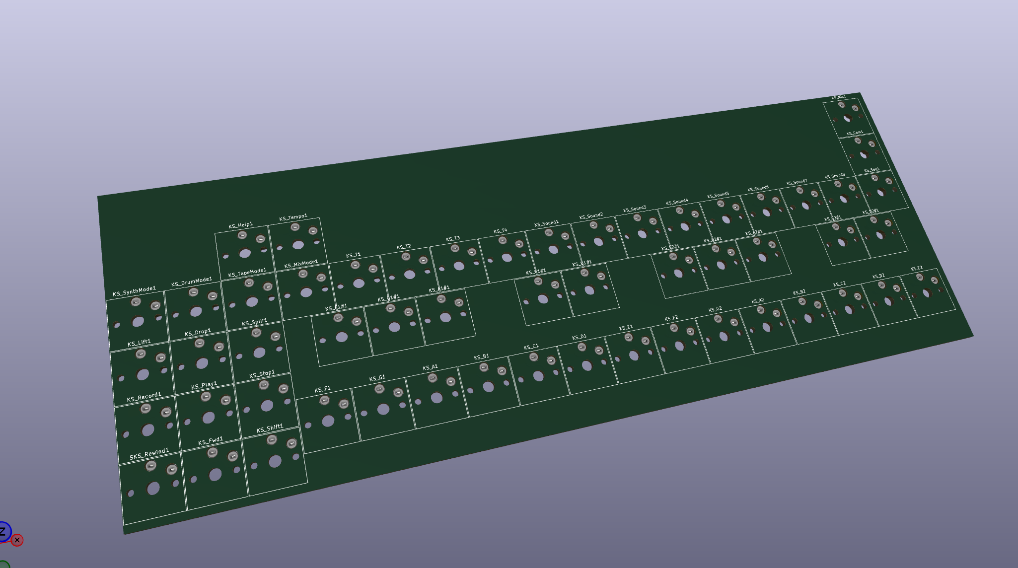
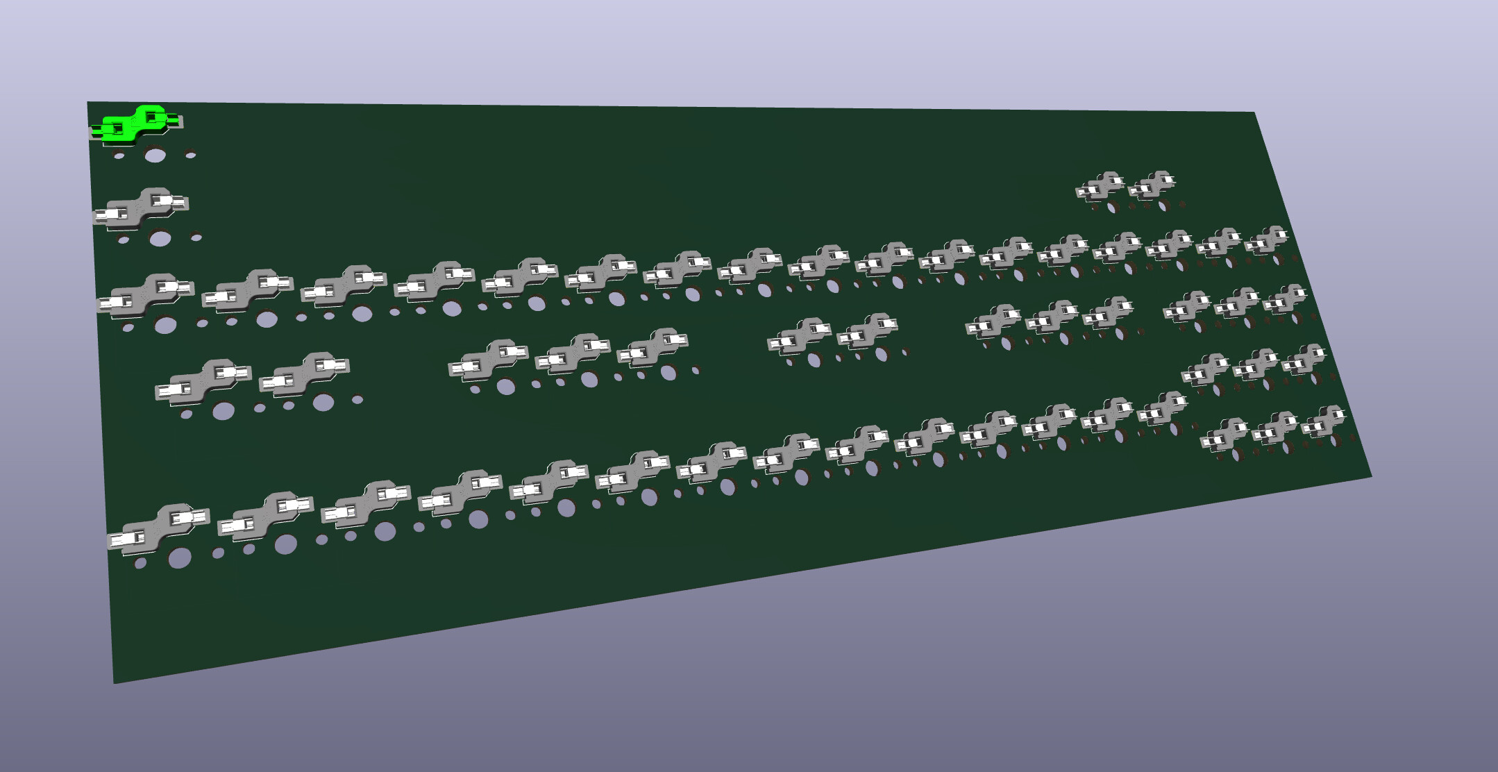
Hey! I worked some more on the original pcb design. I think I’m 70% there (excluding traces, but those I hope to import from the website). Cutouts around buttons and most holes are present now but I need to recheck all the dimensions. The measurements of the spacings on my design are still all over the place but I hope the get it done by tomorrow. Its painful to measure these one by one.
@surfacenormal That looks really good!! I think https://jlcpcb.com/ offers flexpcbs too so maybe its possible to order them in bulk for an okish price
Thats how it looks atm. New file is on github
2 Likes
heck yeah!
I noticed the sketch in your file isn’t watertight, and so isn’t being recognized as a fill shape, and some of the locations are a tiny bit off here and there. Just concerned because alignment has to be bang-on for this to all work properly.
I’m not a super expert at KiCad, but generally these sorts of complex sketches are waaaayyyy easier in traditional parametric CAD programs like Fusion 360 or similar. If you want, maybe I throw it in there, fix it up, and then reimport when you’re done sketching everything out?
And yeah agreed; the flexpcb part of it won’t be hard. The hard part is finding a source for 3x3mm domes.
Sounding like maybe we provide two options here, yeah? I bet the standard pcb option will be done first, and then the more oem replacement will take more revisions to zero in on.